-
Temperature /Humidity Range~200℃~300℃~400℃~500℃
-
Heating TimeRT+10℃~200℃ 25min/RT+10℃~500℃ 50min
-
Heating ModePID + S.S.R.
-
Accuracy±0.1℃; ±1.0℃
-
Uniformity2.5%
-
Inner Size40L, 72L, 270L, 1000L, Etc
-
Available ForScrew,nut,shim,etc
-
Average Filtration Rate99%
-
Cv Precision≤1%
-
Working Resistance10 Pa
-
Surrounding EquipmentsRectifiers Filter Tank Chiller
-
Heating ModelElectronic, Steam
-
Application AreaPlating Chemicals And Water Treatment
-
ProductnameElectroplating Equipment
-
Plating ProcessChrome Zinc Nickle ABS Plating
-
TypeHang Plating / Barrel Plating
-
Filter Groove1-2 Ton
-
Plating MethodBarrel Plating And Hang Plating
-
Machinery Test ReportProvided
-
ApplicationLiquid Filtration
-
Mechanical SealMechanical Seal /packing Seal
-
Place of OriginCHINA
-
Brand NameFENGFAN
-
Model NumberProgrammable Drying Oven
-
Minimum Order QuantityNegotiable
-
PriceNegotiable
-
Packaging DetailsStandard export packaging
-
Delivery Time15-25 work days
-
Payment TermsL/C,D/A,D/P,T/T,Western Union,MoneyGram
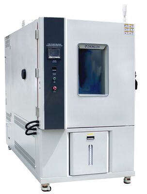
Programmable Constant Temperature and Humidity Test Chamber
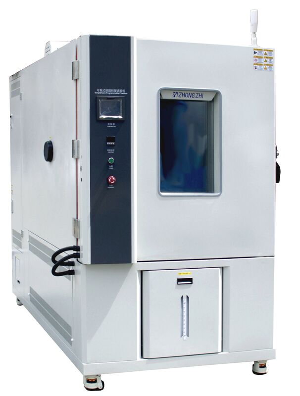
Programmable Constant Temperature and Humidity Test Chamber
|
I. Main functions and precautions for use of the equipment |
|||||||||||||||||||||||||||||||||||||||||||||||||||||||||||||||||||||||||||||||||||||||||||||||||||||||||||||||||||||||||||||||||||||||||||||
|
1. product overview |
This series of products is primarily used to simulate the harsh high-temperature, low-temperature, and humid environments that electronic instruments, new materials, electrical equipment, vehicle components, metals, electronic products, and aerospace materials may encounter during transportation, storage, and use; or in alternating high-temperature and low-temperature conditions. They are designed to test the material, component, or instrument's resistance to high temperatures, cold, and humidity, as well as potential damage and reduced lifespan |
||||||||||||||||||||||||||||||||||||||||||||||||||||||||||||||||||||||||||||||||||||||||||||||||||||||||||||||||||||||||||||||||||||||||||||
|
2. product function |
This series of temperature laboratory is suitable for the reliability test of industrial products, with the characteristics of temperature control accuracy and wide control range. The performance index meets the requirements of GB/T5170 "Verification method of basic parameters of environmental test equipment for electrical and electronic products-Low temperature, high temperature and constant temperature test equipment". |
||||||||||||||||||||||||||||||||||||||||||||||||||||||||||||||||||||||||||||||||||||||||||||||||||||||||||||||||||||||||||||||||||||||||||||
|
3. test sample restrictions |
Test and storage of flammable, explosive and volatile substance samples Test and storage of corrosive material samples Testing or storage of biological samples Test and storage of samples with strong electromagnetic emission sources |
||||||||||||||||||||||||||||||||||||||||||||||||||||||||||||||||||||||||||||||||||||||||||||||||||||||||||||||||||||||||||||||||||||||||||||
|
4. load condition requirements |
The total mass of the load shall not exceed 50Kg per cubic meter of studio volume The total volume of the load is not greater than 1/5 of the studio volume On any section perpendicular to the prevailing wind direction, the sum of the load areas shall not be greater than that at the site The cross-sectional area of the studio is 1/3. The load should not block the flow of air when placed |
||||||||||||||||||||||||||||||||||||||||||||||||||||||||||||||||||||||||||||||||||||||||||||||||||||||||||||||||||||||||||||||||||||||||||||
|
II. Equipment installation site and operating environment conditions |
|||||||||||||||||||||||||||||||||||||||||||||||||||||||||||||||||||||||||||||||||||||||||||||||||||||||||||||||||||||||||||||||||||||||||||||
|
1. site requirements
|
A: not less than 800mm B: not less than 500mm C: not less than 1500mm The ground is flat and well ventilated There is no strong vibration around the equipment There is no strong electromagnetic field around the equipment There is no flammable, explosive, corrosive substances and dust around the equipment Leave appropriate space around the equipment for use and maintenance |
||||||||||||||||||||||||||||||||||||||||||||||||||||||||||||||||||||||||||||||||||||||||||||||||||||||||||||||||||||||||||||||||||||||||||||
|
2. ambient condition
|
Temperature: 5~30℃, relative humidity less than 85%RH Air pressure: 86kPa~106kPa |
||||||||||||||||||||||||||||||||||||||||||||||||||||||||||||||||||||||||||||||||||||||||||||||||||||||||||||||||||||||||||||||||||||||||||||
|
3. maximum power |
The total installed 7.1 Kw is 1.5Kw for cooling power, 2.8Kw for heating power, 1.8KW for humidification power and 0.2Kw for other power |
||||||||||||||||||||||||||||||||||||||||||||||||||||||||||||||||||||||||||||||||||||||||||||||||||||||||||||||||||||||||||||||||||||||||||||
|
4. maximum current |
≤22A |
||||||||||||||||||||||||||||||||||||||||||||||||||||||||||||||||||||||||||||||||||||||||||||||||||||||||||||||||||||||||||||||||||||||||||||
|
5. equipment humidification and water supply |
The water supply pressure is 0.2~0.4Mpa, the water supply pipe diameter is 20mm, and the water quality of the water supply should meet the third-level water standard specified in GB/T 6682-2008 Analytical Laboratory Water Specifications and Test Methods. The equipment has a reserved water supply interface of 1/2" internal thread, and the equipment is equipped with a water tank with a volume of about 20L |
||||||||||||||||||||||||||||||||||||||||||||||||||||||||||||||||||||||||||||||||||||||||||||||||||||||||||||||||||||||||||||||||||||||||||||
|
6. drainage outlet |
A drain is provided near the equipment, within 2 meters behind the equipment, Note: Guide the condensate and water from the meter to flow out of the tank |
||||||||||||||||||||||||||||||||||||||||||||||||||||||||||||||||||||||||||||||||||||||||||||||||||||||||||||||||||||||||||||||||||||||||||||
|
7. power supply conditions and power sources |
AC380V Three-phase four-wire + protective grounding Voltage allowable fluctuation range: ±10%V Frequency allowable fluctuation range: (50±0.5)HZ Power supply in TN-S mode or TT mode The grounding resistance of the protective earth wire is less than 4Ω Users are required to configure the corresponding capacity of air or power switch for the equipment at the installation site, and this switch must be independently controlled for the use of the equipment |
||||||||||||||||||||||||||||||||||||||||||||||||||||||||||||||||||||||||||||||||||||||||||||||||||||||||||||||||||||||||||||||||||||||||||||
|
III. Volume and size |
|||||||||||||||||||||||||||||||||||||||||||||||||||||||||||||||||||||||||||||||||||||||||||||||||||||||||||||||||||||||||||||||||||||||||||||
|
1. model |
CZ-A-225G |
||||||||||||||||||||||||||||||||||||||||||||||||||||||||||||||||||||||||||||||||||||||||||||||||||||||||||||||||||||||||||||||||||||||||||||
|
2. equipment volume |
225L |
||||||||||||||||||||||||||||||||||||||||||||||||||||||||||||||||||||||||||||||||||||||||||||||||||||||||||||||||||||||||||||||||||||||||||||
|
3. size of the test chamber |
W (width) 500 mm * H (height)750 mm * D (depth) 600 mm |
||||||||||||||||||||||||||||||||||||||||||||||||||||||||||||||||||||||||||||||||||||||||||||||||||||||||||||||||||||||||||||||||||||||||||||
|
4. external dimensions of the test chamber |
W (width) 700 mm * H (height) 1850 mm * D (depth) 1660 mm Note: The size of the part beyond the machine door hinge is not included! Please confirm the external dimensions according to the final design three-view drawing! |
||||||||||||||||||||||||||||||||||||||||||||||||||||||||||||||||||||||||||||||||||||||||||||||||||||||||||||||||||||||||||||||||||||||||||||
|
VI. Main performance parameters |
|||||||||||||||||||||||||||||||||||||||||||||||||||||||||||||||||||||||||||||||||||||||||||||||||||||||||||||||||||||||||||||||||||||||||||||
|
1. test condition |
The temperature performance test is measured according to the relevant provisions of GB/T 5170.2-2017 Temperature Test Equipment when the ambient temperature is +25℃ and the load is empty; the sensor is placed at the air handling unit outlet |
||||||||||||||||||||||||||||||||||||||||||||||||||||||||||||||||||||||||||||||||||||||||||||||||||||||||||||||||||||||||||||||||||||||||||||
|
2. temperature range |
-70℃ ~ +150℃ |
||||||||||||||||||||||||||||||||||||||||||||||||||||||||||||||||||||||||||||||||||||||||||||||||||||||||||||||||||||||||||||||||||||||||||||
|
3. humidity range |
|
||||||||||||||||||||||||||||||||||||||||||||||||||||||||||||||||||||||||||||||||||||||||||||||||||||||||||||||||||||||||||||||||||||||||||||
|
4. temperature fluctuation |
≦±0.5℃ |
||||||||||||||||||||||||||||||||||||||||||||||||||||||||||||||||||||||||||||||||||||||||||||||||||||||||||||||||||||||||||||||||||||||||||||
|
5. temperature uniformity |
≤2.0℃ (no load) |
||||||||||||||||||||||||||||||||||||||||||||||||||||||||||||||||||||||||||||||||||||||||||||||||||||||||||||||||||||||||||||||||||||||||||||
|
6. temperature departure |
≥±2.0℃ (no load) |
||||||||||||||||||||||||||||||||||||||||||||||||||||||||||||||||||||||||||||||||||||||||||||||||||||||||||||||||||||||||||||||||||||||||||||
|
7. relative humidity fluctuation |
≦±2.5%R.H |
||||||||||||||||||||||||||||||||||||||||||||||||||||||||||||||||||||||||||||||||||||||||||||||||||||||||||||||||||||||||||||||||||||||||||||
|
8. humidity deviation |
≥75%RH,≤+2-3%R.H; <75%RH ,≤±5%R.H; |
||||||||||||||||||||||||||||||||||||||||||||||||||||||||||||||||||||||||||||||||||||||||||||||||||||||||||||||||||||||||||||||||||||||||||||
|
9. heating rate |
≥3℃/min (under the condition of full average no-load) |
||||||||||||||||||||||||||||||||||||||||||||||||||||||||||||||||||||||||||||||||||||||||||||||||||||||||||||||||||||||||||||||||||||||||||||
|
10. cooling rate |
≥1.2℃/min (under the condition of full average no-load) |
||||||||||||||||||||||||||||||||||||||||||||||||||||||||||||||||||||||||||||||||||||||||||||||||||||||||||||||||||||||||||||||||||||||||||||
|
11. working noise |
≥75 dB (measured 1m in front of the equipment gate and 1.2 m above the ground) |
||||||||||||||||||||||||||||||||||||||||||||||||||||||||||||||||||||||||||||||||||||||||||||||||||||||||||||||||||||||||||||||||||||||||||||
|
12. the standard |
GB/T-2423.1-2008 (IEC60068-2-1) Test A: low temperature test method. GB/T-2423.2-2008 (IEC60068-2-2) Test B: high temperature test method. GB/T-2423.3-2016 (IEC60068-2-78:2012) Environmental Test Part 2 Test Method Test Cab constant humidity and heat test. GB/T-2423.4-2008 (IEC60068-2--30:2005) Environmental test for electrical and electronic products Part 2: Test method Test Db: Alternating humidity and heat (12h+12h cycle) GJBl50.3-2009 (MIL-STD-810D) high temperature test method. GJBl50.4-2009 (MIL-STD-810D) low temperature test method. |
||||||||||||||||||||||||||||||||||||||||||||||||||||||||||||||||||||||||||||||||||||||||||||||||||||||||||||||||||||||||||||||||||||||||||||
|
13. test method |
GB/T-10586-2008 Technical conditions of low temperature test chamber GB/T 5170.1-2016 Inspection method for environmental test equipment of electrical and electronic products-Part 1: General rules GB/T 5170.2-2017 Environmental test equipment inspection method Part 2: Temperature test equipment GB/T 5170.5-2016 Environmental test equipment for electrical and electronic products-Inspection method-Part 5: Wet heat test equipment GB/T5170.18-2005 Basic parameter verification method of environmental test equipment for electrical and electronic products temperature/humidity combination cycle test equipment |
||||||||||||||||||||||||||||||||||||||||||||||||||||||||||||||||||||||||||||||||||||||||||||||||||||||||||||||||||||||||||||||||||||||||||||
|
V. Chamber structure characteristics |
|||||||||||||||||||||||||||||||||||||||||||||||||||||||||||||||||||||||||||||||||||||||||||||||||||||||||||||||||||||||||||||||||||||||||||||
|
1. test chamber structure layout |
The test chamber adopts the integrated structure layout, with the test chamber in front and the control chamber at the back; The bottom of the equipment is equipped with Foma casters to facilitate the relocation, positioning of the equipment The outer chamber of the equipment is made of cold-rolled steel plate baked paint, with a thickness of 1.2mm and a light gray color number RAL7035. The inner chamber is made of SUS304# stainless steel with a thickness of 1.2mm; The equipment adopts frame structure as a whole, and the bottom of the chamber is welded with channel steel to increase the strength of the chamber Insulation material: hard polyurethane hard foam + glass fiber 100mm thick The rear of the equipment is equipped with a total power protection circuit breaker, power supply cable and drainage pipe The chamber door seal adopts silicone sealing strip, which is specially customized and has high temperature resistance, non-toxicity and ultra-flexibility The bottom of the inner chamber is equipped with a drainage hole, which can quickly discharge the condensate An automatic pressure relief hole is set at the top of the chamber |
||||||||||||||||||||||||||||||||||||||||||||||||||||||||||||||||||||||||||||||||||||||||||||||||||||||||||||||||||||||||||||||||||||||||||||
|
2. drain off water |
The bottom of the inner chamber is equipped with a drainage hole, and the drainage system is arranged on the rear side of the equipment. The drainage pipe is introduced into the drainage pipe network system of the user (the user provides the on-site drainage pipe network interface) |
||||||||||||||||||||||||||||||||||||||||||||||||||||||||||||||||||||||||||||||||||||||||||||||||||||||||||||||||||||||||||||||||||||||||||||
|
3. pressure relief hole |
Multiple pressure balance Windows are set on the edge of the back of the chamber. When the switch chamber door is opened or the air inside the chamber expands, the pressure can be quickly and automatically discharged; |
||||||||||||||||||||||||||||||||||||||||||||||||||||||||||||||||||||||||||||||||||||||||||||||||||||||||||||||||||||||||||||||||||||||||||||
|
4. chamber door |
Single hinge door, effective clear size W500mm*H750mm The door material is the same as the body material Imported door lock, open on the outside The insulation material with a thickness of 100mm is rigid polyurethane foam A water collection tray is designed below the door to prevent the condensation water from falling on the outdoor ground; |
||||||||||||||||||||||||||||||||||||||||||||||||||||||||||||||||||||||||||||||||||||||||||||||||||||||||||||||||||||||||||||||||||||||||||||
|
5. inner chamber material |
SUS304# stainless steel plate is used, precision laser cutting equipment is used to cut and CNC folding bed bending, and then argon arc welding is used for full welding, polishing and polishing; the steel plate is 1.2mm thick; sample rack pallet support indexing frame is set on both sides of the inner chamber, which can adjust the spacing between sample racks |
||||||||||||||||||||||||||||||||||||||||||||||||||||||||||||||||||||||||||||||||||||||||||||||||||||||||||||||||||||||||||||||||||||||||||||
|
6. outer chamber material |
Using cold-rolled steel plates, precision laser cutting equipment is employed for cutting and CNC folding for shaping, followed by welding and polishing with argon arc welding; after the steel plate surface undergoes overall acid washing to remove rust, it is then treated with high-temperature baking paint. Compared to conventional exterior painting, this method results in a more aesthetically pleasing appearance and enhanced corrosion resistance. The steel plate thickness is 1.2mm (color: RAL7035 white). |
||||||||||||||||||||||||||||||||||||||||||||||||||||||||||||||||||||||||||||||||||||||||||||||||||||||||||||||||||||||||||||||||||||||||||||
|
7. sealing joint strip |
The door sealing strip is divided into two layers, the inner layer is a silicon rubber strip that can fully isolate the inner chamber from the outside under high and low temperature conditions; the silicone rubber strip can work for a long time without hardening and aging in the range of minus 80℃ to plus 200℃; |
||||||||||||||||||||||||||||||||||||||||||||||||||||||||||||||||||||||||||||||||||||||||||||||||||||||||||||||||||||||||||||||||||||||||||||
|
8. stainless steel hinges |
On the left side of the chamber door, a set of high strength hinges are installed. A single hinge can withstand 3 tons of force horizontally and continue to bend in the opposite direction. The two pieces of the hinge completely deform and merge into one without breaking; |
||||||||||||||||||||||||||||||||||||||||||||||||||||||||||||||||||||||||||||||||||||||||||||||||||||||||||||||||||||||||||||||||||||||||||||
|
9. door handle |
The door lock is a roller tightening door lock: The chamber door is used both inside and outside, using the principle of lever, with strong urgency, saving force, and can be opened and closed with one hand. |
||||||||||||||||||||||||||||||||||||||||||||||||||||||||||||||||||||||||||||||||||||||||||||||||||||||||||||||||||||||||||||||||||||||||||||
|
10. air outlet structure |
The forced internal circulation mode with strong wind circulation is adopted, in which the air goes out at the top and returns at the bottom. The guide plate of the outlet can distribute the cold and hot air to the whole interior of the storage body, which is uniform and stable |
||||||||||||||||||||||||||||||||||||||||||||||||||||||||||||||||||||||||||||||||||||||||||||||||||||||||||||||||||||||||||||||||||||||||||||
|
11. aluminum wind wheel |
Multi-wing centrifugal circulating aluminum wind wheel has the characteristics of light weight, large air volume, high wind pressure, and is resistant to high and low temperature, small expansion coefficient and low operating noise. |
||||||||||||||||||||||||||||||||||||||||||||||||||||||||||||||||||||||||||||||||||||||||||||||||||||||||||||||||||||||||||||||||||||||||||||
|
12. observation window |
The box door is equipped with a multi-layer hollow large glass observation window, featuring an electric heating (automatically adjustable) anti-frosting and anti-condensation device. The window is equipped with a set of window lighting lamps, allowing you to clearly observe the test status of the samples inside the box through the observation window at any time. |
||||||||||||||||||||||||||||||||||||||||||||||||||||||||||||||||||||||||||||||||||||||||||||||||||||||||||||||||||||||||||||||||||||||||||||
|
13. instrument connection |
One hole is opened on the left side of the chamber, with a diameter of 100mm, and a hole cover and silica gel plug are provided |
||||||||||||||||||||||||||||||||||||||||||||||||||||||||||||||||||||||||||||||||||||||||||||||||||||||||||||||||||||||||||||||||||||||||||||
|
14. test the material rack |
The SUS304# stainless steel is punched and bent into a mesh, which is easy to use. The spacing between the material racks can be adjusted at least 45mm, and two sample racks are standard |
||||||||||||||||||||||||||||||||||||||||||||||||||||||||||||||||||||||||||||||||||||||||||||||||||||||||||||||||||||||||||||||||||||||||||||
|
15. principle of air circulation |
High power fan driven by external motor with stainless steel shaft, fan motor is external; The air is driven by the motor and flows through the heater and refrigeration evaporator. After being fully heated/ cooled to the required temperature value, the air circulates inside the chamber and exchanges heat with the specimen through convection The air is forced to circulate by using a low voltage asynchronous high temperature resistant long shaft motor Multi-wing centrifugal circulation fan is used, and aluminum alloy blades stir the air |
||||||||||||||||||||||||||||||||||||||||||||||||||||||||||||||||||||||||||||||||||||||||||||||||||||||||||||||||||||||||||||||||||||||||||||
|
16. principle of temperature control system |
High quality nickel-chromium alloy wire electric heater, SSR control, equipped with independent overtemperature protection temperature switch When the heater is energized, the surface temperature will rise. The convection air is heated by the heating wire, and the heat is expanded to the air and the specimen in the chamber, so as to heat and warm up. The heating power is precisely controlled by PID algorithm, and the output power is adjusted by solid state relay. The refrigeration system provides sufficient low-temperature refrigerant to the heat exchanger, so that the temperature of the heat exchanger is lower than the air temperature. The heat in the air is absorbed and carried out of the chamber by the heat exchanger, so that the air temperature drops and the cooling effect is achieved. The cooling power is precisely controlled by PID algorithm, and the refrigerant flow and cooling capacity are adjusted by solenoid valve. |
||||||||||||||||||||||||||||||||||||||||||||||||||||||||||||||||||||||||||||||||||||||||||||||||||||||||||||||||||||||||||||||||||||||||||||
|
VI. Refrigeration system |
|||||||||||||||||||||||||||||||||||||||||||||||||||||||||||||||||||||||||||||||||||||||||||||||||||||||||||||||||||||||||||||||||||||||||||||
|
1. refrigeration compressor |
|
||||||||||||||||||||||||||||||||||||||||||||||||||||||||||||||||||||||||||||||||||||||||||||||||||||||||||||||||||||||||||||||||||||||||||||
|
2. cooling-down method |
|
||||||||||||||||||||||||||||||||||||||||||||||||||||||||||||||||||||||||||||||||||||||||||||||||||||||||||||||||||||||||||||||||||||||||||||
|
3. evaporimeter |
|
||||||||||||||||||||||||||||||||||||||||||||||||||||||||||||||||||||||||||||||||||||||||||||||||||||||||||||||||||||||||||||||||||||||||||||
|
4. throttling set |
|
||||||||||||||||||||||||||||||||||||||||||||||||||||||||||||||||||||||||||||||||||||||||||||||||||||||||||||||||||||||||||||||||||||||||||||
|
5. refrigerator control mode |
The programmable logic controller of the control system automatically adjusts the operating condition of the refrigeration machine according to the test conditions Compressor return gas cooling circuit |
||||||||||||||||||||||||||||||||||||||||||||||||||||||||||||||||||||||||||||||||||||||||||||||||||||||||||||||||||||||||||||||||||||||||||||
|
6. imported refrigeration accessories |
|
||||||||||||||||||||||||||||||||||||||||||||||||||||||||||||||||||||||||||||||||||||||||||||||||||||||||||||||||||||||||||||||||||||||||||||
|
7. evaporative condenser |
|
||||||||||||||||||||||||||||||||||||||||||||||||||||||||||||||||||||||||||||||||||||||||||||||||||||||||||||||||||||||||||||||||||||||||||||
|
8. cryogen |
Use R404a/R23, an environmentally friendly refrigerant with ozone depletion index of 0 |
||||||||||||||||||||||||||||||||||||||||||||||||||||||||||||||||||||||||||||||||||||||||||||||||||||||||||||||||||||||||||||||||||||||||||||
|
9. nitrogen filling welding process |
It is recommended to use high quality oxygen-free copper pipe for low temperature coupling pipeline, and the welding quality of the pipeline, nitrogen filling and 48-hour high pressure leakage prevention process should be ensured. |
||||||||||||||||||||||||||||||||||||||||||||||||||||||||||||||||||||||||||||||||||||||||||||||||||||||||||||||||||||||||||||||||||||||||||||
|
10. energy saving control |
The application of cold balancing technology in refrigeration systems can save approximately 30% of electrical energy, effectively reducing operating costs. As shown in the figure above, thermal balancing is achieved by adjusting the amount of heating output to maintain a constant temperature. This means that with a fixed compressor cooling capacity, the heating will increase over time, leading to wasted energy and unnecessary expenses for users. In contrast, cold balancing technology maintains a constant temperature by adjusting the compressor cooling capacity. When the temperature approaches the set point, the cooling capacity gradually decreases through PID regulation to achieve a stable temperature (theoretically, zero heating output can be achieved, but in actual production, there is always a small amount of heating output), thus achieving the goal of energy conservation |
||||||||||||||||||||||||||||||||||||||||||||||||||||||||||||||||||||||||||||||||||||||||||||||||||||||||||||||||||||||||||||||||||||||||||||
|
11. features of refrigeration system
|
A. The whole system pipeline is tested for leakage by pressurizing 22kg. B. The heating and cooling systems are completely independent. C. Equipped with the company's professional technical characteristics, it prevents high temperature and high pressure air flow from damaging the refrigeration system. D. All the freezing system operation procedures are completely controlled by the microcomputer controller. E. The bottom of the compressor has a water tray, which can collect the condensation water produced by frosting. F. The compressor has its own PTC temperature sensor, which can realize over-temperature protection when the compressor is overheated. G. The compressor has its own oil pressure protector to realize the oil pressure protection of the compressor. H. High and low pressure protection devices monitor the pressure of refrigerant during the operation of the equipment. Once the pressure of refrigerant is higher than the limit pressure of the system or lower than the minimum pressure set by the system, an alarm will be issued immediately and the power supply will be cut off until the fault is removed. I. The refrigeration system uses imported brand parts, reliable quality, to ensure the stability of the system. |
||||||||||||||||||||||||||||||||||||||||||||||||||||||||||||||||||||||||||||||||||||||||||||||||||||||||||||||||||||||||||||||||||||||||||||
|
VII. Electrical control system |
|||||||||||||||||||||||||||||||||||||||||||||||||||||||||||||||||||||||||||||||||||||||||||||||||||||||||||||||||||||||||||||||||||||||||||||
|
1. controller |
|
||||||||||||||||||||||||||||||||||||||||||||||||||||||||||||||||||||||||||||||||||||||||||||||||||||||||||||||||||||||||||||||||||||||||||||
|
2. run mode |
Program operation, fixed value operation. The whole process of intelligent PID automatic control |
||||||||||||||||||||||||||||||||||||||||||||||||||||||||||||||||||||||||||||||||||||||||||||||||||||||||||||||||||||||||||||||||||||||||||||
|
3. control model |
The humidity and temperature combination control/single temperature control is automatically adjusted according to the humidity set value |
||||||||||||||||||||||||||||||||||||||||||||||||||||||||||||||||||||||||||||||||||||||||||||||||||||||||||||||||||||||||||||||||||||||||||||
|
4. language |
It has a switch display between Chinese, English and Russian |
||||||||||||||||||||||||||||||||||||||||||||||||||||||||||||||||||||||||||||||||||||||||||||||||||||||||||||||||||||||||||||||||||||||||||||
|
5. set mode |
Human-machine dialogue operation interface, touch input |
||||||||||||||||||||||||||||||||||||||||||||||||||||||||||||||||||||||||||||||||||||||||||||||||||||||||||||||||||||||||||||||||||||||||||||
|
6. temperature and humidity input |
Grade PT100 A precision platinum resistance |
||||||||||||||||||||||||||||||||||||||||||||||||||||||||||||||||||||||||||||||||||||||||||||||||||||||||||||||||||||||||||||||||||||||||||||
|
7. display resolution |
Temperature: 0.01℃; humidity: 0.1%RH; time: 1min; |
||||||||||||||||||||||||||||||||||||||||||||||||||||||||||||||||||||||||||||||||||||||||||||||||||||||||||||||||||||||||||||||||||||||||||||
|
8. program capacity and control function |
The maximum number of programs that can be used: 100 sets, one program can be composed of 1 to 100 segments; the command can be repeated up to 999 times, the slope setting of the program can be set by the time axis, each segment between programs can be set to a maximum of 99 hours and 99 minutes, a minimum of one minute, and can be set for joint use It features editing, clearing, and insertion functions. It has time signal output control (for controlling the ON/OFF actions of the object under test). During program execution, it supports skipping segments and holding functions. The screen can be adjusted for backlighting, with adjustable backlight duration settings. The screen display protection function allows for timed or manual shutdown settings. Program replication, COPY, connection functions, and program editing functions such as setting experiment titles are available. It includes power-off program memory, automatic restart upon reconnection, and scheduled startup and shutdown functions. Date and time adjustment functions, key and screen lock (LOCK) functions, and standby image viewing functions are also provided |
||||||||||||||||||||||||||||||||||||||||||||||||||||||||||||||||||||||||||||||||||||||||||||||||||||||||||||||||||||||||||||||||||||||||||||
|
9. output control mode |
PID+SSR output automatic control; PID automatic adjustment of heating output; refrigeration has cold end and multi-channel electronic expansion valve control, which can set the corresponding valve to adjust the compressor working condition according to the suction and exhaust temperature and pressure of the compressor. Electronic expansion valve control can switch between evaporating pressure control and conventional temperature control |
||||||||||||||||||||||||||||||||||||||||||||||||||||||||||||||||||||||||||||||||||||||||||||||||||||||||||||||||||||||||||||||||||||||||||||
|
10. communication function |
Can connect to computer to display curve and data acquisition; Can be used as monitoring and remote control system; Multiple machines can be controlled synchronously; RS-485/RS-232 RJ45 Ethernet port USB joggle. |
||||||||||||||||||||||||||||||||||||||||||||||||||||||||||||||||||||||||||||||||||||||||||||||||||||||||||||||||||||||||||||||||||||||||||||
|
11. U disk storage |
It can be plugged into 1G-32G USB to download historical curves, historical data, control system parameters, and hot-swappable function |
||||||||||||||||||||||||||||||||||||||||||||||||||||||||||||||||||||||||||||||||||||||||||||||||||||||||||||||||||||||||||||||||||||||||||||
|
12. method of data recording |
The RAM with battery protection can save the device's set value, sampling value and sampling time for 8-10 years; the curve recording period can be set from 30 to 180 sec, and the maximum memory time can store continuous historical curves for 90 days. The historical data (when the sampling time is 1min) can be saved for more than 10 years without continuous use |
||||||||||||||||||||||||||||||||||||||||||||||||||||||||||||||||||||||||||||||||||||||||||||||||||||||||||||||||||||||||||||||||||||||||||||
|
13. power off memory function |
The power failure recovery mode can be set as: hot start/cold start/stop. |
||||||||||||||||||||||||||||||||||||||||||||||||||||||||||||||||||||||||||||||||||||||||||||||||||||||||||||||||||||||||||||||||||||||||||||
|
14. reservation start function |
The start-up time can be set at will. After the power is turned on, the machine will automatically run when the time is up. |
||||||||||||||||||||||||||||||||||||||||||||||||||||||||||||||||||||||||||||||||||||||||||||||||||||||||||||||||||||||||||||||||||||||||||||
|
15. software compatible systems |
Windows Operating system |
||||||||||||||||||||||||||||||||||||||||||||||||||||||||||||||||||||||||||||||||||||||||||||||||||||||||||||||||||||||||||||||||||||||||||||
|
16. open software functions |
Supports third-party upper-level sending code to control the device start, stop, and data recording functions Note: The controller provides functional codes, and the user can edit the upper computer software program to realize unified monitoring and control |
||||||||||||||||||||||||||||||||||||||||||||||||||||||||||||||||||||||||||||||||||||||||||||||||||||||||||||||||||||||||||||||||||||||||||||
|
17. network connections |
|
||||||||||||||||||||||||||||||||||||||||||||||||||||||||||||||||||||||||||||||||||||||||||||||||||||||||||||||||||||||||||||||||||||||||||||
|
18. situation display |
At the top of the equipment, a cylindrical three-color sound and light alarm (using LED beads) is installed; when waiting for startup or operation completion, the yellow light is always on; when running normally, the green light is always on; when emergency stop or equipment fault alarm, the red light is always on and the buzzer is intermittent; |
||||||||||||||||||||||||||||||||||||||||||||||||||||||||||||||||||||||||||||||||||||||||||||||||||||||||||||||||||||||||||||||||||||||||||||
|
19. circulating fan |
High temperature resistant, long shaft motor, the motor is installed in the outdoor space, the shaft extends to the indoor, the stirring fan wheel is installed at the tail end of the shaft; special heat insulation measures and heat dissipation system improve the safety of the motor. |
||||||||||||||||||||||||||||||||||||||||||||||||||||||||||||||||||||||||||||||||||||||||||||||||||||||||||||||||||||||||||||||||||||||||||||
|
20. heating control mode |
The temperature controller sends commands based on the set temperature and signals from the temperature sensor inside the test chamber. It regulates the output of the heater through a logic circuit, controlling the SSR module. The system operates reliably, with no contacts or sparks, long life, low noise, and no electromagnetic interference. It features fast switching speed, strong anti-interference capability, compact size, vibration resistance, impact resistance, explosion-proofing, moisture-proofing, and corrosion resistance. It achieves direct control of high-current loads using minimal control signals. |
||||||||||||||||||||||||||||||||||||||||||||||||||||||||||||||||||||||||||||||||||||||||||||||||||||||||||||||||||||||||||||||||||||||||||||
|
VIII. Safety protection system |
|||||||||||||||||||||||||||||||||||||||||||||||||||||||||||||||||||||||||||||||||||||||||||||||||||||||||||||||||||||||||||||||||||||||||||||
|
1. overtemperature protection |
The test chamber is equipped with an independent adjustable electronic over-temperature protection device and automatic pressure balance protection. |
||||||||||||||||||||||||||||||||||||||||||||||||||||||||||||||||||||||||||||||||||||||||||||||||||||||||||||||||||||||||||||||||||||||||||||
|
2. refrigeration system |
Compressor overheating, high pressure protection, motor overcurrent protection. |
||||||||||||||||||||||||||||||||||||||||||||||||||||||||||||||||||||||||||||||||||||||||||||||||||||||||||||||||||||||||||||||||||||||||||||
|
3. circulating fan |
overload protection |
||||||||||||||||||||||||||||||||||||||||||||||||||||||||||||||||||||||||||||||||||||||||||||||||||||||||||||||||||||||||||||||||||||||||||||
|
4. calorifier |
Extreme overtemperature protection: short circuit protection |
||||||||||||||||||||||||||||||||||||||||||||||||||||||||||||||||||||||||||||||||||||||||||||||||||||||||||||||||||||||||||||||||||||||||||||
|
5. humidification system |
Humidifier dry burn water shortage protection, humidifier extreme temperature protection, humidifier short circuit protection |
||||||||||||||||||||||||||||||||||||||||||||||||||||||||||||||||||||||||||||||||||||||||||||||||||||||||||||||||||||||||||||||||||||||||||||
|
6. general supply |
Leakage protection, overload and short circuit protection, phase loss, reverse phase, undervoltage, overvoltage protection |
||||||||||||||||||||||||||||||||||||||||||||||||||||||||||||||||||||||||||||||||||||||||||||||||||||||||||||||||||||||||||||||||||||||||||||
|
7. control circuit |
Overload and short circuit protection |
||||||||||||||||||||||||||||||||||||||||||||||||||||||||||||||||||||||||||||||||||||||||||||||||||||||||||||||||||||||||||||||||||||||||||||
|
8. compressor cooling system |
Overload protection of cooling fan |
||||||||||||||||||||||||||||||||||||||||||||||||||||||||||||||||||||||||||||||||||||||||||||||||||||||||||||||||||||||||||||||||||||||||||||
|
IX. Acceptance standards and third-party verification 1. Acceptance criteria: Technical indicators shall be in accordance with the methods specified in the "Technical Agreement" signed by both parties. 2. Acceptance method: formal acceptance shall be carried out on the site of the buyer. 3. Before delivery, the buyer shall invite a third party (calibrated by the National Environmental Test Equipment Quality Testing Center and issued with a valid inspection report) to participate The acceptance fee shall be borne by the buyer. If the first acceptance is not qualified, the cost incurred in the second acceptance after the supplier's improvement shall be borne by the supplier Funds to be borne by the party concerned. 4. The customer shall entrust the National Environmental Test Equipment Quality Testing Center to verify the equipment |
|||||||||||||||||||||||||||||||||||||||||||||||||||||||||||||||||||||||||||||||||||||||||||||||||||||||||||||||||||||||||||||||||||||||||||||
|
X.List of main materials
|
|||||||||||||||||||||||||||||||||||||||||||||||||||||||||||||||||||||||||||||||||||||||||||||||||||||||||||||||||||||||||||||||||||||||||||||
|
XI. Equipment factory supporting devices and data 1. Equipment factory packing list 1 copy 2. Equipment and electrical schematic diagram 1 copy 3. Equipment instruction manual 1 copy 4. Equipment certificate 1 copy 5. Equipment warranty card 1 copy 6. Equipment factory test report 1 copy 7. Wet gauze 5 pieces 8. Controller monitoring software CD-ROM 1 piece 9. Test sample rack tray 2 pieces 10. Test sample rack support track bar 4 strips |
|||||||||||||||||||||||||||||||||||||||||||||||||||||||||||||||||||||||||||||||||||||||||||||||||||||||||||||||||||||||||||||||||||||||||||||
|
XII. Quality assurance and service commitment 1. Purpose: In line with the concept of mutual benefit and win-win service, fully meet customer needs and achieve the purpose of customer satisfaction. 2. Pre-sale: professional technical consultation, product test plan proposal, test chamber installation and construction plan; 3. In sale: customer communication, progress report, guidance, installation, debugging, trial operation, etc., cooperate with customer measurement; 4. Training(domestic China, foreignal countries need to be negotiated with seller): According to the contract requirements, on-site training can be carried out when the equipment is installed and debugged for the user and put into use; users can be arranged to come to the company for on-site technical training when the equipment is debugged at the factory, so that customers can understand the performance of the equipment, train the correct use method, reduce the failure caused by improper use of the equipment, and save maintenance costs for customers; 5. After-sales Service: Technical Training: Operation and use, daily maintenance and care, common fault detection and troubleshooting; Regular Follow-ups: Equipment inspection, fault elimination, transmission of the latest industry information; Specialized Spare Parts and Accessories Reserve Support; Dedicated After-sales Service Department Maintenance Personnel to ensure timely and effective fault resolution, providing swift repair services; 6. Service Commitment(domestic China, foreignal countries need to be negotiated with seller): Method: 7x24 hour customer service hotline and dedicated service email; Requirements: Provide a clear response within 4 hours. For on-site services, require 24-hour arrival within the province and 24 hours outside the province; from Dongguan or local company offices, dedicated personnel will be responsible for sales and after-sales service of the company's products in the region; based on specific circumstances, repair time can be negotiated according to the needs of the client; from the date of acceptance, during the one-year warranty period, our company will provide free repairs (excluding damage caused by natural disasters, power abnormalities, improper use, or maintenance). If the equipment fails to function properly due to manufacturing quality issues of the test chamber under conditions where the client complies with storage, usage, and installation rules, the supplier will dispatch maintenance personnel for free repairs upon notification, in accordance with the service commitment timeline. After the warranty period, if any issues arise with the equipment, the supplier commits to promptly addressing them and may charge for repair and material costs as appropriate. |
|||||||||||||||||||||||||||||||||||||||||||||||||||||||||||||||||||||||||||||||||||||||||||||||||||||||||||||||||||||||||||||||||||||||||||||
|
XIII. Packaging and transportation: 1. Packaging: transport packaging chamberes that meet the requirements of QB/BWD008-2001 2. Mode of transport: by truck |
|||||||||||||||||||||||||||||||||||||||||||||||||||||||||||||||||||||||||||||||||||||||||||||||||||||||||||||||||||||||||||||||||||||||||||||
|
XIV. Chamber structure diagram
|
|||||||||||||||||||||||||||||||||||||||||||||||||||||||||||||||||||||||||||||||||||||||||||||||||||||||||||||||||||||||||||||||||||||||||||||
Our products are sold all over the world, you can rest assured.